LED signals
The EtherCAT Status and Link/Activity LEDs functionality is specified according to the "EtherCAT Indicator Labeling Specification" defined by the EtherCAT Technology Group.
|
LED states |
Slave State |
|---|---|
|
Off |
INITIALISATION |
|
Blinking |
PREOPERATIONAL |
|
Single Flash |
SAFEOPERATIONAL |
|
On |
OPERATIONAL |
|
Flickering |
INITIALISATION or BOOTSTRAP |
EtherCAT ERROR Status (red)
|
ERR State |
Error Name |
|---|---|
|
On |
Application controller failure |
|
n Flashes |
Reserved |
|
Triple Flash |
Reserved |
|
Double Flash |
Process Data Watchdog Timeout / EtherCAT Watchdog Timeout |
|
Single Flash |
Local Error |
|
Blinking |
Invalid Configuration |
|
Flickering |
Booting Error |
|
Off |
No error |
EtherCAT Link/Activity
|
Link |
Activity |
Condition |
Link/Activity Code |
|---|---|---|---|
|
Yes |
No |
Port open |
On |
|
Yes |
Yes |
Port open |
Flickering |
|
No |
Not applicable |
Port closed |
Off |
|
Yes |
Yes/No |
Port closed (mode needs manual open) |
Inverted double flash |
|
No |
No |
Local PHY auto negotiation error |
Single Flash |
|
No |
No |
Remote PHY auto negotiation |
Double Flash |
|
No |
No |
Unknown PHY auto negotiation |
Triple Flash |
For more information refer to the WorkBench online help.
MKD-C
|
|
The LED 7-segment display indicates the status of the drive after the 24 V supply is switched on. MKD fault codes or warning codes are displayed constantly if present. Fault messages are coded with "F" or "E", warnings are coded with "n". The IP address can be flashed across the 7-segment display by pressing B1 Push-button (B1). The IP address can be configured with rotary switch S1 Rotary Switch (S1), Setting IP address. |
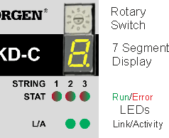
EtherCAT STAT LEDs: There is one LED per string. As the LED is a bi-colored LED, it is used to display both the RUN (Green) and Error (RED) status.
EtherCAT L/A LEDs: These are the EtherCAT Link/Activity LEDs associated with the Motion Bus IN (X10) and OUT (X11) ports. Activity description seetable above.
MKD-N
|
|
DRIVE LEDs: There is one LED per Axis. The LED delivers information with three colors (red, green, orange) and blink frequency (see WorkBench Help).
|
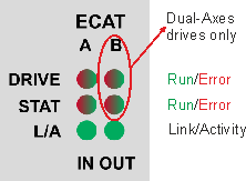
Local Fieldbus STAT LEDs: There is one LED per Axis. As the LED is a bi-colored LED, it is used to display both the RUN (Green) and Error (RED) status.
Local Fieldbus L/A LEDs: These are the Link/Activity LEDs associated with the Local Fieldbus Bus IN (X27) and OUT (X28) ports. Activity description see EtherCAT RUN Status (green).
RJ45 LED signals
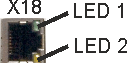
MKD-C, X18 (Service)
|
LED# |
Name |
Function |
|
|---|---|---|---|
|
LED1 |
Link |
ON = active, OFF= not active |
|
LED2 |
Activity |
ON = running, OFF = not running |
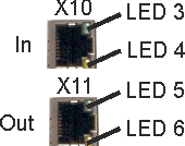
MKD-C, X10, X11 (Motion Bus)
|
LED# |
Name |
Function |
|
|---|---|---|---|
|
LED3 |
Link |
ON = active, OFF= not active |
|
LED4 |
- |
- |
|
|
LED5 |
Link |
ON = active, OFF = not active |
|
|
LED6 |
- |
- |
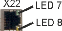
MKD-C, X22 (local fieldbus out)
|
LED# |
Name |
Function |
|
|---|---|---|---|
|
LED7 |
Link |
ON = active, OFF= not active |
|
LED8 |
- |
- |
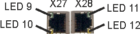
MKD-N, X27, X28 (local fieldbus in/out)
|
LED# |
Name |
Function |
|
|---|---|---|---|
|
LED9 |
Link |
ON = active, OFF= not active |
|
LED10 |
Activity |
ON = running, OFF = not running |
|
|
LED11 |
Link |
ON = active, OFF = not active |
|
|
LED12 |
- |
- |